
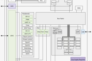
And one of these is the i-o state machine, of which there are eight. spread over two ‘PIO blocks’ – (one shown right).
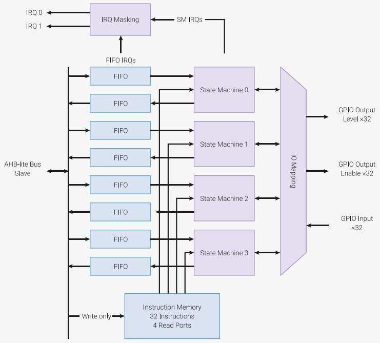
According to the RP2040 data sheet, the four state machines simultaneously execute programs from a shared instruction memory. FIFO data queues buffer data transferred between PIO and the system. GPIO mapping logic allows each state machine to observe and manipulate up to 30 GPIOs.
They can be used to implement simple serial bust standards and other functions including a VGA video interface – I am now wondering if these state-machines could be used to add some anti-shoot-through timing for the PWM outputs – a need I was pondering in January
UPDATE: we asked and got a reply from a spokesman: “I’ve had some information back from the guys who designed these parts of the chip. The PWM’s themselves do not have any dead-band facilities. There is no way of combining the PIO and PWM in the way you want. However, we think it should be possible to do something like this using two PIO’s channels to introduce the dead-band, which would be in 10’s of ns range.”
According to the Foundation: “If you are ever tempted to ‘bit-bang’ a protocol on RP2040, don’t. Use the PIO instead. Frankly this is true for anything that repeatedly reads or writes from GPIOs, but certainly anything which aims to transfer data.”
This is what the Raspberry Pi Pico C/C++ SDK datasheet has to say about PIO blocks:
The PIO subsystem on RP2040 allows you to write small, simple programs for what are called PIO state machines, of which RP2040 has eight split across two PIO instances. A state machine is responsible for setting and reading one or more GPIOs, buffering data to or from the processor (or RP2040 DMA sub-system), and notifying the processor, via IRQ or polling, when data or attention is needed. These programs operate with cycle accuracy at up to system clock speed.
PIO state machines are similar in size to a standard SPI peripheral, such as the PL022 SPI also found on RP2040, because much of their area is spent on components which are common to all serial peripherals, like FIFOs, shift registers and clock dividers.
A PIO state machine gets a lot more done in one cycle than a Cortex-M0+ when it comes to I/O: for example, sampling a GPIO value, toggling a clock signal and pushing to a FIFO all in one cycle, every cycle. Programming a PIO state machine is quite familiar for anyone who has written assembly code before. For simple hardware protocols – such as PWM or duplex SPI – a single PIO state machine can handle the task of implementing the hardware interface all on its own. For more involved protocols such as SDIO or DPI video you may end up using two or three.
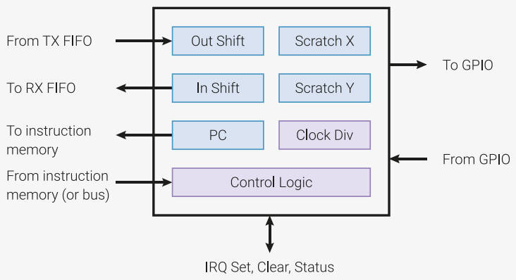
- 2x 32bit shift registers – either direction, any shift count
- 2x 32bit scratch registers
- 4x 32bit bus transmit FIFO
- 4x 32bit bus transmit FIFO
- 4x 32bit bus transmit FIFO plus
4x 32bit bus receive FIFO
(can be reconfigured as 8×32 one direction) - Fractional (16 integer, 8 fractional bit) clock divider
- GPIO mapping
- DMA interface, up to one word per clock from system DMA
- IRQ flag set/clear/status
To manipulate them there are nine instructions: JMP, WAIT, IN, OUT, PUSH, PULL, MOV, IRQ and SET – with libraries available for common functions like serial bus interfaces.
‘pioasm’ is an assembler provided in the SDK for writing i-o code.
Hats off to the clever folk at Raspberry Pi.
I was struggling to cope with the PIO as the documentation is very poor. For me
https://www.amazon.com/Programming-Raspberry-Pi-Pico-C/dp/1871962684/
by Harry Fairhead was a life saver.
Disclosure — I have known Harry at a distance for a while I wonder why he
seems to be below the radar most of the time?
These look very similar to what we used to call Programmable Logic Controllers, or PLC’s for short. They were used for controlling factory machinery and were thus ruggedly constructed and adequately EMC-proof. Peripherals included relays, electro-valves (for pneumatic actuators), lights, alarm sounders, push-buttons, foot switches, electric motors, all the usual stuff.
PLCs were made by several companies including Texas Instruments, Allen-Bradley, and GEC. My favourite was the GEC GEM-80.
Programming was usually accomplished using ladder-diagrams. Later PLC’s had timers, PWM, serial comms etc all built in.
They were eventually superseded by industrial-grade computers.
Oops! Slipped up there! ‘EMC-proof’ would be a bad thing to have… I should have written ‘with suitable EMC capabilities’ instead of ‘adequately EMC-proof’. Sorry, chaps.