 One area of interest for electric vehicle (EV) manufacturers looking to improve performance in safe and cost-effective ways is improving battery management systems (BMS). These work in real time to monitor the performance of individual battery cells within the EV. By effectively monitoring each battery cell, an EV’s microcontroller can ensure the proper operation of all battery cells and balance load sharing.
Distributed BMS in EVs
In electrified automotive applications, internal battery packs can extend up to 800V to support the demanding loads of the AC motor. This translates into potentially 100 or more lithium-ion cells stacked together in series inside the vehicle chassis.
These high-voltage packs increasingly require more sophisticated technologies to report cell diagnostics in a safe, timely and reliable manner. One common design technique is to implement a distributed battery pack system, which supports high-cell count packs by connecting multiple battery monitors on separate PCBs.
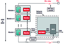
In a wired BMS, connecting these monitors in a daisychain with twisted pair cabling enables the propagation of data acquired for each module of battery cells. The difference between a wired and wireless BMS is that the latter uses a wireless communications interface rather than daisychain cabling (Figure 1).
In Figure 1, there is a subsystem containing the host microcontroller, which interfaces with the control unit of the vehicle through a controller area network bus. The microcontroller processor drives the battery monitor devices connected to the battery modules to sense voltage and temperature. Depending on how many channels the battery monitors support, there can be any number of devices stacked to support high-voltage packs, which all need to communicate back to the host microcontroller quickly.
Other common aspects of the system requiring monitoring and communications include high-voltage relay controls to ensure safe disconnection of the high voltage when the vehicle is not in use, and current sensing to calculate the state of charge and the state of health of the battery pack.
The comms interface
With regard to the communications interface between each battery monitor device connected in the pack and the host microcontroller, a typical wired solution connects battery monitors in a daisychain cable with twisted-pair cabling between battery modules and a wireless microcontroller for transmitting data.
For a wireless implementation, a wireless interface is used to transmit universal asynchronous receiver transmitter (UART) data from the battery monitor to the host microcontroller via a wireless transceiver device.
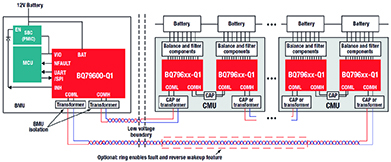
Figure 3 uses a more simplified representation of a CMU than in Figure 1, but adds a wireless receiver node to show that the CMU has an additional device to transmit cell data wirelessly back to the host. This enables the two CMUs shown in Figure 2 to be naturally isolated from one another.
The significant difference between the two versions comes down to the replacement of the twisted-pair cabling in the wired design with, in this case, a CC2642R-Q1 SimpleLink Bluetooth 5.1 low energy wireless microcontroller on each BMU in the wireless design.
It may appear that adding an extra device may create more complexity and cost more than cabling, but this can be countered with the cost and weight of the cabling and the need to place high-performance isolation components on either side of the twisted-pair interface to ensure communication robustness.
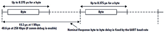
These TX and RX functions are controlled automatically by the hardware based on the device’s base or stack detection, and the data is reclocked as it propagates to each module. The RX topology of the BQ796xx devices used in this example is similar to RS-485, but with added design mechanisms to attenuate high common-mode voltages caused by the noisy conditions typical in vehicle environments. Each byte transmits at 2MHz (250ns per pulse or 500ns per couplet). As shown in Figure 4, the time between each byte depends on the UART baud rate (1Mbps in normal operation), but the byte time is always the same.
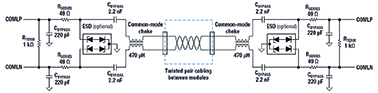
The wired interface is designed to support capacitive or inductive isolation for robustness amid stringent automotive EMC/EMI specification limits. Figure 5 shows an example using capacitors and chokes. The circuit would be designed between each battery monitor PCB, with as many as 64 devices in one stack to support varying sizes of vehicle battery modules.
Texas Instruments developed a proprietary wireless BMS protocol based on Bluetooth Low Energy operating in the 2.4GHz frequency band.
The key difference between the two protocols is the daisychain twisted-pair wiring propagating the signal from the microcontroller to the top monitor and back down. In a wireless star network configuration, each individual module can communicate independently back to the host processor.
Both versions provide specifications that are highly important for automotive systems to deliver large amounts of pertinent battery pack data quickly, safely and reliably.
Table: Considerations for wired vs wireless battery management
Considerations Wired BMS Wireless BMS
Weight n Typical reliability standard
n Increases overall vehicle weight and complexity n Decreases overall vehicle weight and complexity
Design flexibility and serviceability n Less flexibility with a larger overall footprint
n More difficult to service
n Modular once cables are disconnected n Smaller footprint enables design flexibility and more flexible placement within the vehicle
n Easier to service
Measurement n Time-synchronised measurements of voltage and current must propagate all the way up and down, causing delay between readings
n Delayed measurement feature can improve performance n Wireless system naturally enables time-synchronised measurements
n Offers the ability to add more synchronised sensing capabilities
Reliability n Wiring is reliable and meets functional safety standards, but can break over time
n Ring architecture features built-in redundant cables in both directions
n Can be more complex to repair n No wires to maintain
n Design must overcome harsh automotive radio-frequency environments and non-line-of-sight challenges
Security n Contained and fully secure system communication n Possible to breach poorly designed systems that lack security protocols